
Studying chemistry, one of the lightbulb moments was the realisation that lab skills weren't about learning how to use techniques, but instead about learning how to avoid stuffing things up, and rescue things once they were stuffed up. As the saying goes: "In theory, there's no difference between theory and practice. In practice, there's a world of difference." Genarally speaking, the Amateur Radio exams give the new constructor all the theory they need to start building their own equipment. However, that doesn't mean it's easy to go from idea to circuit, or from circuit to understanding so I thought I'd ramble my way through a couple of vaguely useful circuits.
As far as I can see, the training manuals only introduce the Colpitts Oscillator. There are of course plenty of good reasons, and it's probably the simplest good general purpose oscillator. However, it can be a little difficult to relate the theory to what exactly is going on, and a special purpose oscillator may be easier to understand.
The Barkhausen criteria states that for a negative feedback
system, oscillation will occur when the loop gain has a phase shift
of 180 degrees and a magnitude of unity or greater. In short you
need a tuned circuit and a feedback amplifier. In practice this is
true too. It's just that dealing with real-world parts is a little
more complicated than the books usually let on! Hence the search
for the simplest oscillator... 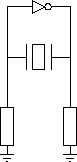
The Pierce Oscillator is the simplest oscillator I could find.
Unfortunatly this simplicity generally restricts its use to crystal
tuned circuits, and it doesn't play nicely with LC tuned circuits.
However, it does consist of the simplest possible tuned circuit and
feedback oscillator. It's also nice and easy to build. The circuit
consists of a crystal, and an inverter (grounded so we get a
useable signal). The output can be taken from anywhere in the
circuit, since one side is the inverse of the other 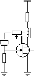
Going from functional diagram to schematic should be quite simple. This one was adapted from Dr Calvert's version.
Looking at the diagram on the left, the grounding
resistor on the left remains, and the one on the right is replaced
by the JFET drain-source impedance. The inverter is provided by the
voltage divider created between the JFET and the supply choke
feeding back through the variable resistor and DC-blocking
capacitor. 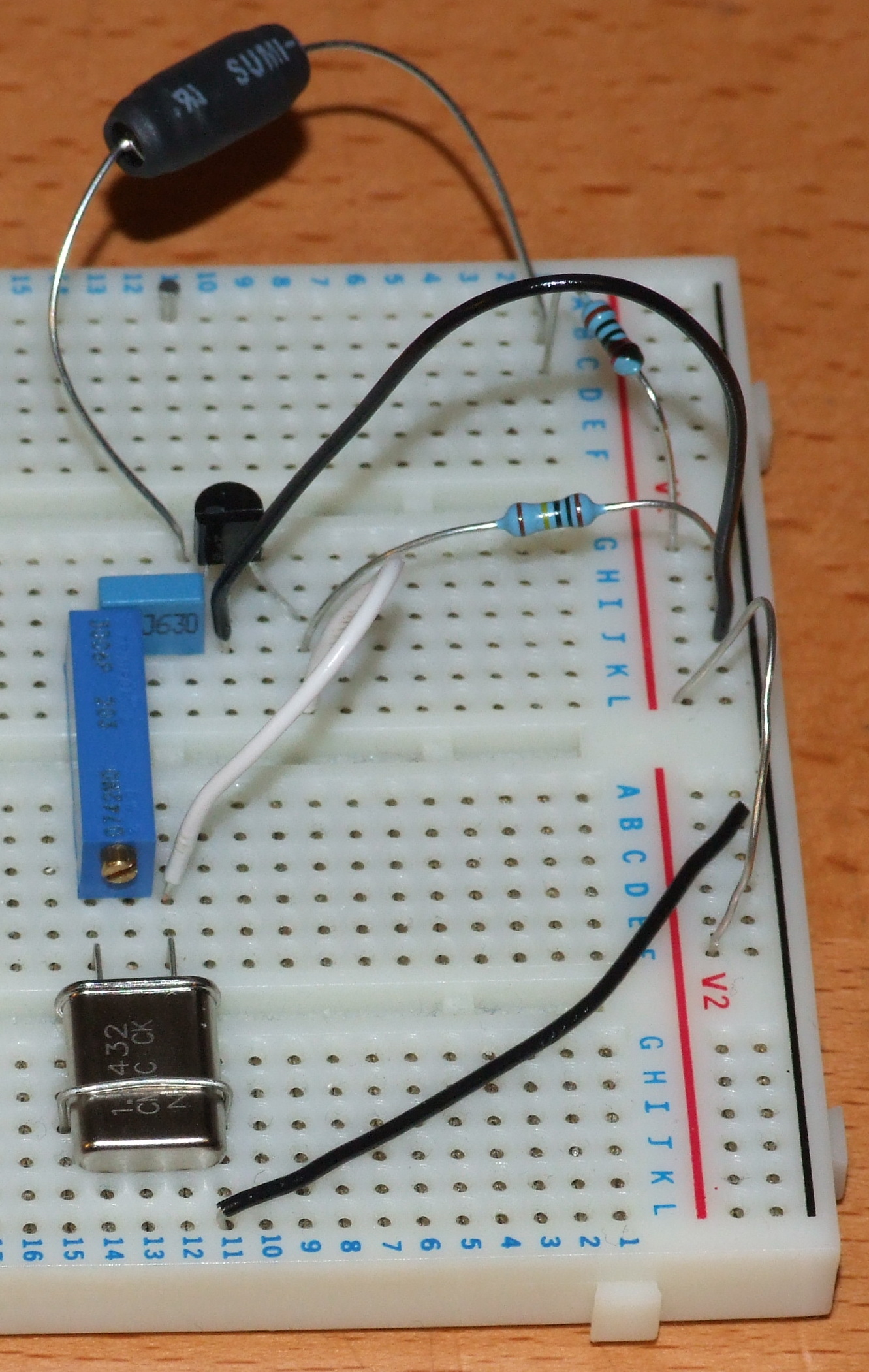
A variable resistor was used in this case so that the feedback could be adjusted easily. I also replaced the 10M ground-coupling resistor with a 1M one. Not for any theoretical reason, but simply because I didn't have any 10M ones, and 1M was near enough for what it was doing! The limiting resistor was added between the choke and supply rail to pretect the JFET, and the choke. This was a later revision, after I tried moving the design to soldered stripboard; the first FET was damaged, and shorted to ground. This caused more current to flow than the choke was designed for, and so caught fire while I was diagnosing the problem... The other unexpected bit of practicaility was the need to ground the crystal can. The variable resistor was coupling to the can, and reducing the feedback so the oscillation never started. The grounding issue was diagnosed by poking bits of the circuit and seeing what happened, and the coupling to the variable resistor was discovered in a later version where it was replaced by a fixed resistor and the grounding was found to be unnecessary. 1.8432 MHz was chosen as the crystal frequency since it was readily available, and is conveniently in the 160m all modes segment. It's a useful frequency for modern computer equipment, and so is eaily available and reasonably cheap.
Breadboard is quite a useful tool for working up circuits. The ability to plug and unplug components means that circuits can be worked up without thinking too hard in advance, and the can be fixed and adjusted far more easily than soldering allows. The similarity in layout to stripboard also means that layouts can be tested before comitting them to solder.
At this point, there's enough stray signal, that one can simply connect the circuit to 12-15V, and one should be able to receive the carrier if it's sat next to an HF receiver set to CW and tuned to 1.8432 MHz. Since the feedback on this circuit is quite brutal, one can also hear it on 3.6864MHz, 5.5296MHz, 7.3728MHz, and 9.216MHz! (But only if you're within a few metres.) In some ways, this harmonic distortion is bad, because the harmonics normally need filtered out hence the low-pass filters you always see on amplifiers. In other ways, it's good; it's impractical to manufacture a crystal for 144MHz, but it's relatively easy to manufacture one for 36MHz, and take the fourth harmonic. Indeed, several steps of frequency multiplication is how crystal controlled microwave transmitters are built, and Amateur microwave handbooks typically list the steps to go from common crystals to the Amateur microwave bands.
One of the things that the training manuals note, is that when building a CW transmitter one should never key the oscillator directly. This is because the oscillator doesn't spin up instantly, and doing so causes chirp on the note as the frequency settles. This sounds bad, and may impact on nearby transmissions. However, since we're currently putting out microwatts, and one needs to be in the same room to pick it up, I thought I'd try it and record the results for you to hear. Similarly, any change in the load on the crystal will pull the frequency, so in order for the signal to be useable what we need is a buffer amplifier with a high (constant) input impedance, and the ability to drive later stages, but that's for another time.