
 There's a range of relatively inexpensive frequency
counters, badge engineered by various companies; Watson, MFJ,
Optoelectronics, etc. that appear to share a lot of common design.
(I suspect that the only thing that changes is the front panel, and
the switches installed.) At least, the Watson FC-130, and the
Optoelectronics Scout 40 seem to share the same front end.
There's a range of relatively inexpensive frequency
counters, badge engineered by various companies; Watson, MFJ,
Optoelectronics, etc. that appear to share a lot of common design.
(I suspect that the only thing that changes is the front panel, and
the switches installed.) At least, the Watson FC-130, and the
Optoelectronics Scout 40 seem to share the same front end.
Unfortunately, that front end is a little fragile. It uses a 50Ω MMIC to terminate the antenna. The upside is that this is quite sensitive and low power. The downside is that it's easily destroyed. For example by plugging it directly into an FM-1000! It would appear that this is a common problem, but in contrast to the likes of Yaesu, etc. the manufacturer takes steps to obscure the workings of the device — going so far as to sand the part numbers off some of the ICs! While the input MMIC wasn't specifically obscured, it isn't a common British part. Or a common part at all, as I finally tracked down the markings (A06Z)in a Russian web forum.
It's an MSA-0611 , apparently available only by import from the US, with attendant substantial shipping charges. They are, at least, a lot cheaper than replacing the entire counter.
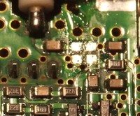 A device this small is quite hard to desolder with
conventional tools, since surface tension in the legs renders them
immune to solder braid. However, since I didn't intend to recover
the device, it was easy enough to apply some larger snips to the
package, reducing the problem to some plastic crumbs and four
slightly pathetic looking legs still attached to the board. These
were easy enough to clean up using a conventional soldering iron
and braid.
A device this small is quite hard to desolder with
conventional tools, since surface tension in the legs renders them
immune to solder braid. However, since I didn't intend to recover
the device, it was easy enough to apply some larger snips to the
package, reducing the problem to some plastic crumbs and four
slightly pathetic looking legs still attached to the board. These
were easy enough to clean up using a conventional soldering iron
and braid.
An MMIC is a Microwave Monolithic Integrated Circuit. This can cover a while lot of applications, but in this case, it's just an improved transistor — effectively just an op-amp. They are more useful than that might suggest, since the package typically contains the biasing circuitry, and matches the input and output to 50Ω, making them useful at any frequency, not just microwave.
They are especially useful at microwave frequencies as the
wavelength approaches a significant fraction of the phase distance
between a conventional transistor and conventional biasing
circuitry. Indeed, at that point one needs to think of all the
interconnects as transmission lines, rather than just wires. The
move to SMT components isn't just to make things difficult to
repair!
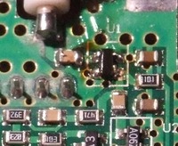 Soldering in SMD components has
been covered in much longer articles in the likes of RadCom, PW,
etc. so I wont labour the point here. The basic procedure is to
place a dab of solder on one of the pads, and solder the single leg
in place. I chose the bottom right one, since it was more
substantial then tha others. One then applies an excess of solder
to the legs on the other side, so that the original dab holds the
device in place. Soldering the pins together is not a problem,
since surface tension draws the solder where it's needed, and the
excess is cleaned off with de-solder braid. Having done this,
proceed to the first side and do the same again.
Soldering in SMD components has
been covered in much longer articles in the likes of RadCom, PW,
etc. so I wont labour the point here. The basic procedure is to
place a dab of solder on one of the pads, and solder the single leg
in place. I chose the bottom right one, since it was more
substantial then tha others. One then applies an excess of solder
to the legs on the other side, so that the original dab holds the
device in place. Soldering the pins together is not a problem,
since surface tension draws the solder where it's needed, and the
excess is cleaned off with de-solder braid. Having done this,
proceed to the first side and do the same again.