
This is a brief howto, to create a basic PowerPole busbar, useful for connecting various bits of kit at temporary locations. It's fairly robust, but not environmentally sealed. It's also not fused, so you need to fuse the supply seperatly.
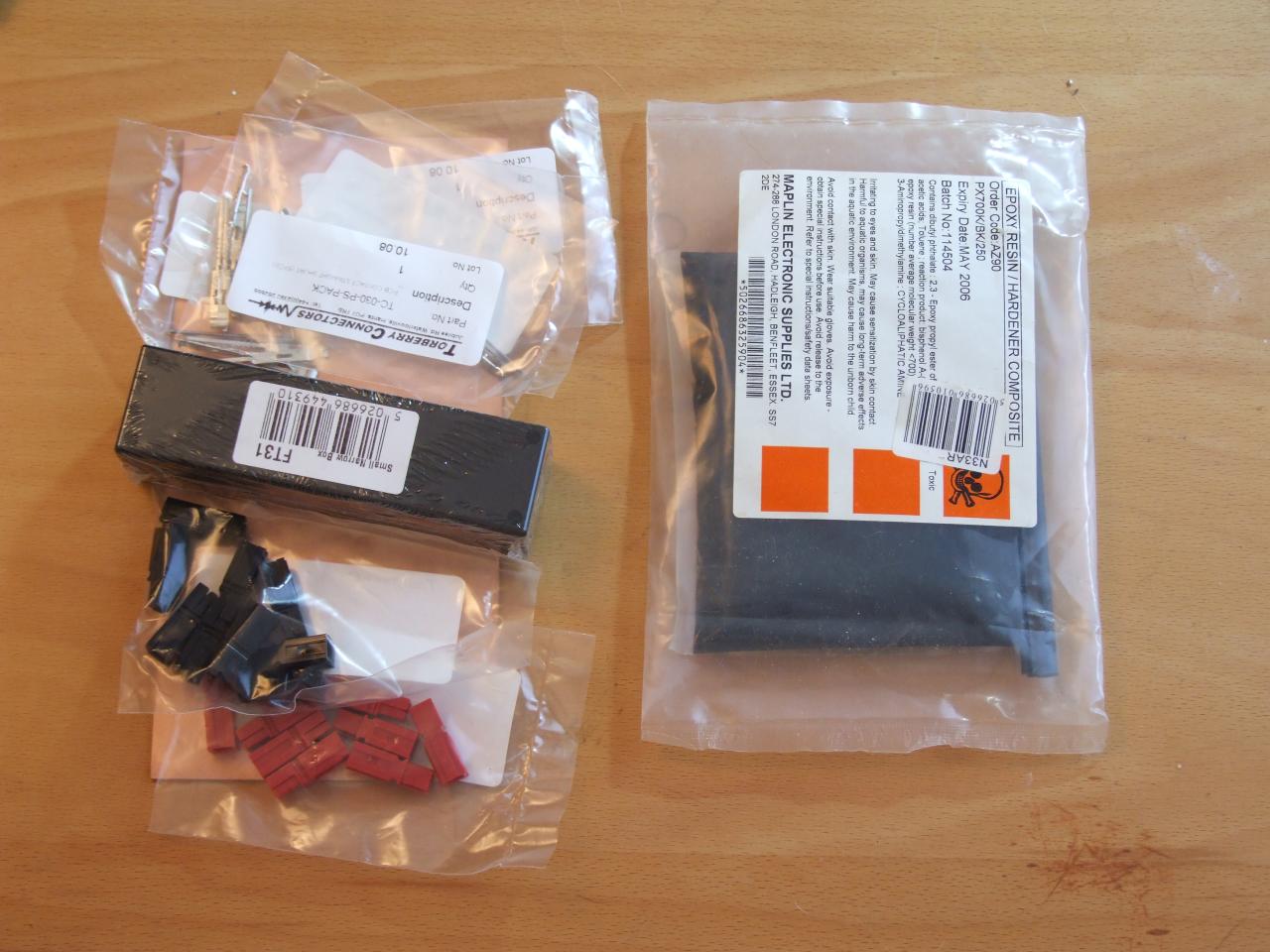
Required parts:
 The first step is
to assemble the powerpoles. If you haven't assembled them before,
it's important to get them the right way round. Have a close look
at the pictures, or a real life example if you have one to hand.
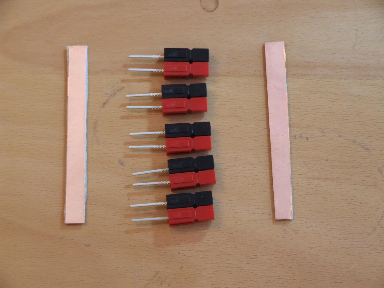
The PCB connectors go in much easier if you have a pair of
needle-nosed pliers. That way, you can hold the tails along the
length of the jaws, and slot them straight in. Make up however many
you'll need. The first one I made took 10 pairs. That was probably
overkill, and means that using them all limits the current it can
reasonably use. For thisone, I chose 5, which seems more sensible.
The current rating is 25A per connector, and probably not much more
in total. 50W V/U units seem to draw about 15A, and something like
the 817 5A max. So if you have a 50W unit, an 817 (or equivalent)
or a small laptop/netbook, a battery, and a solar charger or power
downlink you'll fill the bar without going over.
The first step is
to assemble the powerpoles. If you haven't assembled them before,
it's important to get them the right way round. Have a close look
at the pictures, or a real life example if you have one to hand.
The PCB connectors go in much easier if you have a pair of
needle-nosed pliers. That way, you can hold the tails along the
length of the jaws, and slot them straight in. Make up however many
you'll need. The first one I made took 10 pairs. That was probably
overkill, and means that using them all limits the current it can
reasonably use. For thisone, I chose 5, which seems more sensible.
The current rating is 25A per connector, and probably not much more
in total. 50W V/U units seem to draw about 15A, and something like
the 817 5A max. So if you have a 50W unit, an 817 (or equivalent)
or a small laptop/netbook, a battery, and a solar charger or power
downlink you'll fill the bar without going over.
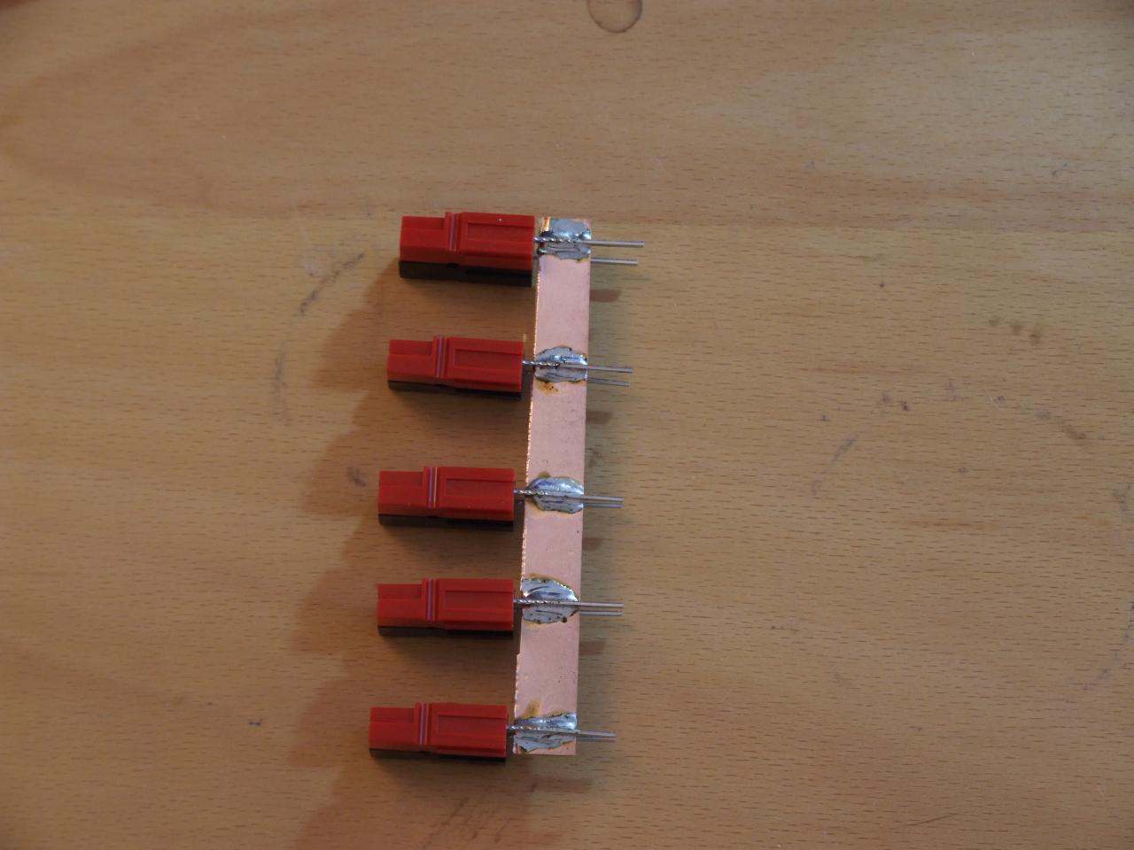 The next step is to cut the PCB into 1cm
x Whatever strips. You'll need two for this - positive and
negative. I cut mine by scoring both sides (through the copper) and
snapping in a vise with the scores along the jaw. Next, solder the
bars to the pins. The first three are fiddly unless you have
suitable helper stands etc. I solder the bars inside because it
seems easier, but you can solder them outside if you think it'll
work better. There's a fair amount of metal, so a powerful iron and
working quickly should get it done solidy without melting the
plastic.
The next step is to cut the PCB into 1cm
x Whatever strips. You'll need two for this - positive and
negative. I cut mine by scoring both sides (through the copper) and
snapping in a vise with the scores along the jaw. Next, solder the
bars to the pins. The first three are fiddly unless you have
suitable helper stands etc. I solder the bars inside because it
seems easier, but you can solder them outside if you think it'll
work better. There's a fair amount of metal, so a powerful iron and
working quickly should get it done solidy without melting the
plastic.
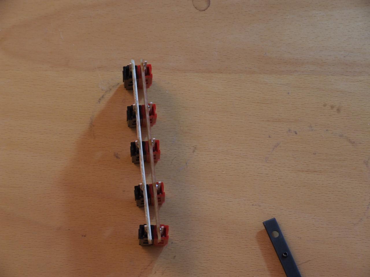 This photo's just another view
of the soldered results, so you can see how I mounted the bars.
Remember to snip the excess pin length.
This photo's just another view
of the soldered results, so you can see how I mounted the bars.
Remember to snip the excess pin length.
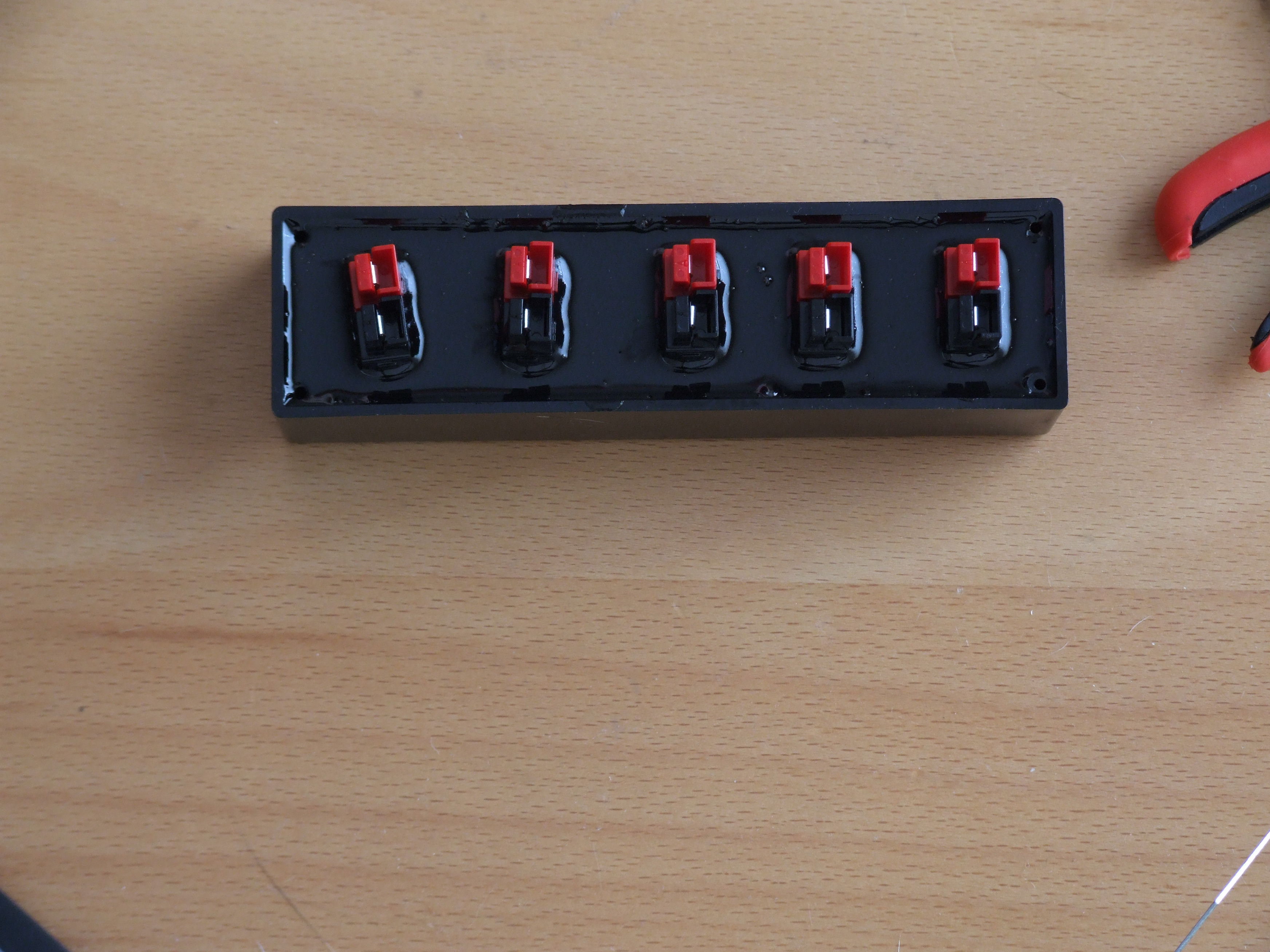 At this point, the hardware is basically
assembled. Put the bar in the case, secure it in place temporarily
since pouring the epoxy usually moves it slightly, and follow the
instructions on the potting compound. If you've ended up with the
same sizes as me, filling the case to the top should be the right
level. Remember not to fill so high it covers any of the mating
surfaces, and careful how you pour for the same reason.
At this point, the hardware is basically
assembled. Put the bar in the case, secure it in place temporarily
since pouring the epoxy usually moves it slightly, and follow the
instructions on the potting compound. If you've ended up with the
same sizes as me, filling the case to the top should be the right
level. Remember not to fill so high it covers any of the mating
surfaces, and careful how you pour for the same reason.
On the subject of fusing: The purpose of a fuse is to protect the operator, and burn out before the wiring catches fire. It isn't to protect the equipment, nor is it a somewhat inconvenient switch. Since this is a single-station busbar, it's sensible to fuse it at the input, since if you blow any fuse, you're off-air anyway. With this design, adding a fuse to the output of the battery, or as the main supply comes into the bar (or both if you have both) is sensible. Fusing probably isn't needed if you're running entirely off small solar and can't put out more than 25A.